

Low voltage switchgear panels play a critical role in the safe and controlled distribution of electrical energy. Circuit breakers, contactors, relays and other electrical components contained in these panels must remain within certain temperature limits in order to operate reliably and continuously. However, the heat increase caused by electrical currents inside the panel can negatively affect the performance of the equipment and even pose serious risks such as fire. Therefore, it is mandatory to apply correct design principles in low voltage panels in order to minimize the effects of temperature increase and ensure system safety.
The main reasons for temperature increase in low voltage panels are:
► Electrical Losses: Resistance-induced heat caused by the current passing in the conductors and connection points used in the panel.
► Inadequate Ventilation: Increase in temperature as a result of the heat generated inside the panel not being able to be discharged.
► Dense Component Placement: Placing electrical equipment too close to each other causes heat to accumulate.
► Ambient Temperature: The temperature of the environment where the panel is installed directly affects the temperature inside the panel.
► Overload and Unbalanced Current Distribution: Loading above normal triggers excessive heat generation.
Thermal Derating and Real Operating Conditions
One aspect that is often underestimated during design is thermal derating. Manufacturers provide nominal current ratings for circuit breakers and busbars, but these values are typically defined under specific reference temperatures. In real installations, especially in industrial plants, ambient temperatures may already be close to the upper operational limit. When multiple devices operate simultaneously under high load, internal temperature rises beyond catalog assumptions. Designers who ignore derating factors may unintentionally push equipment toward continuous thermal stress conditions.
In practice, many overheating issues do not originate from undersized conductors but from increased contact resistance over time. Mechanical vibrations, thermal expansion cycles, and improper torque application during assembly can gradually weaken connections. Even a minor increase in resistance at a bolted joint can create a localized hotspot under high current. These hotspots may not trigger immediate protective action, yet they accelerate oxidation and insulation aging. Preventive torque verification and periodic thermal inspections significantly improve long-term reliability.
Instead of treating the enclosure as a single thermal volume, experienced designers often divide the panel internally into functional heat zones. Power sections, motor feeders, and high-current busbar compartments generate considerably more heat compared to control or signaling sections. By physically separating these zones and using barriers or compartmentalization techniques, internal temperature gradients can be managed more effectively. This approach not only improves cooling efficiency but also protects sensitive electronic devices from unnecessary thermal exposure.
Excessive temperature inside the switchboard can cause the following problems:
► Equipment Damage: Shortened life of electrical components, premature failures.
► Performance Decrease: Incorrect or premature triggering of protection devices.
► Insulation Deterioration: Corrosion of cable and component insulation over time.
► Fire Risk: Increased risk of fire due to heat.
► Loss of Productivity: Increase in electrical losses.
When the causes and effects of temperature increase are taken into consideration, there are points where the effects can be reduced by paying attention when designing. These points are evaluated by the designer and the temperature increase can be reduced with the optimum solution and the negative effects of the temperature increase can be reduced.
Appropriate Conductor Selection
The selection of components to be used in the panel is selected by taking into account the nominal current value to be carried in the panel, but the material selection must be made without ignoring the temperature effect. For example, for energy transfer to a power circuit with fixed busbar connection, the aluminum raw material conductor must be minimum 16mm.2 If the copper conductor is a minimum of 10mm2 It is specified in IEC 60364.¹ When choosing a material, the designer must also consider the effects of the selected component.
In addition, when choosing a material at the design stage, the temperature resistance of this material should be taken into consideration. For example, the surface temperature of bare copper busbars during operation is specified as a maximum of 105°C in IEC 61439-1 Chapter 8.7. In line with this limit, a designer who designs a label for the busbar must choose the material of the label to be used by choosing a material above the highest temperature specified in IEC 61439-1. (e.g. Acrylate permanent)
Verification and Type Testing Considerations
Temperature rise performance should not rely solely on theoretical calculations. Verification through type testing or comparison with previously tested assemblies provides stronger confidence. In compliance with IEC 61439, temperature rise limits must be validated under defined load conditions. Designers who reference tested configurations instead of building entirely new layouts reduce uncertainty and approval risks. Documentation of these verification steps also strengthens technical credibility during inspections.
Impact of Harmonics on Thermal Behavior
Modern installations increasingly include nonlinear loads such as variable speed drives and switched-mode power supplies. These loads introduce harmonic currents into the system. Harmonics increase RMS current values and may cause additional heating, particularly in neutral conductors and transformer windings. In panels where harmonic content is significant, conductor sizing and thermal evaluation should account for these effects. Ignoring harmonics can lead to unexpected temperature rise even when nominal current limits appear acceptable.
Device Layout Planning
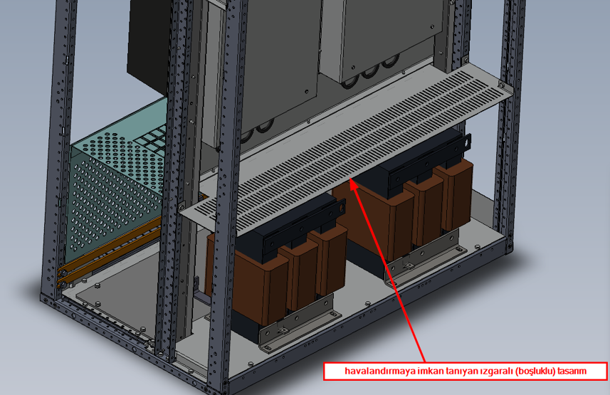
The aim should be to reduce heat intensity by leaving sufficient distance between electrical components. Heat producing devices such as contactors, switches, fuses, transformers, frequency converters, harmonic filters should be placed in upper sections or separate areas within the panel, if possible. The minimum clearance distances specified in the manufacturer’s catalogs of the devices to be used should be taken into consideration during placement. Heat-generating devices should not be placed on top of each other and the devices should not be covered. If they will be covered due to partitioning, partitioning should be done with a grid design.
Ventilation and Cooling
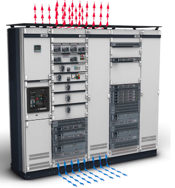
Natural or fan ventilation systems should be used to remove the heat inside the panel. The temperature can be kept balanced with vents, fans or thermostat-controlled cooling systems. In fan systems, fans automatically activate when the temperature inside the panel exceeds a certain threshold, expelling hot air and allowing cool air to flow from the outside environment.
Evaluation of Environmental Conditions
The temperature and humidity of the panel installation location should be taken into consideration, and environmental factors such as direct sunlight and excessive dust should be avoided. Additionally, the IP (Ingress Protection) protection classes on the panels should be taken into consideration when designing.² Since the IP degree directly affects the openings of the air intake vents, it must be taken into consideration by the designer. This plays a decisive role on the air circulation of the panel. The effect of the ambient temperature on the nominal current should be adjusted by taking into account the manufacturer’s catalogs, and a design selection should be made in accordance with the demand. (IEC 61439-2 Chapter 8 and TS EN 61439-1 chapter 10.3)
While designing, the design should be supported by heat increase tests in which the design is made in accordance with the heating values allowed by the general standard of low voltage switching systems (IEC 61439), or the reference test should be approached with engineering analysis and information should be shared with customers. In addition, within the scope of the same standard, product performance evaluation must be made within the scope of type testing. The type test requirement is shared under the title “Verification of temperature increase” in IEC 61439-1 Part-0, and its details are detailed under the title “Verification methods of temperature increase” in IEC 61439-1 Part-1.⁴’⁵
Maintenance as a Design Parameter
Thermal performance is not determined only at the design stage; it is influenced by maintenance practices throughout the system’s lifetime. Dust accumulation, clogged ventilation filters, and aging cooling fans reduce heat dissipation efficiency. For this reason, maintainability should be considered during the design phase. Easy access to critical connection points, removable ventilation filters, and clear inspection paths make periodic thermal checks more practical. A design that cannot be maintained easily will eventually experience thermal degradation.
Results
Controlling the temperature increase in low voltage switchgear panels is of vital importance for both system safety, long-lasting operation of the equipment and the transfer of the requested nominal current. These risks can be minimized by selecting appropriate components, correct placement, effective ventilation and taking into account environmental conditions during the design process. Type test principles and standards used today enable designers to produce effective solutions in this regard.