Before starting to design a PLC card, it is necessary to ask the following basic question: What is PLC and how does it work??
The answer to this question is not just a technical explanation; It also helps us understand why industrial automation needs these systems.
Why do leading companies in the industry such as Siemens, Rockwell, Schneider, Mitsubishi develop such cards? Why can’t an ordinary microcontroller and a customized board design replace the solutions offered by these companies?
Flexibility in a PLC is not only about being programmable; it is about architectural foresight. A custom microcontroller board often works perfectly—until the first specification change. One more sensor. A different voltage level. A faster response requirement. Suddenly, PCB revisions begin. Industrial PLC cards are designed with margin: electrical margin, timing margin, thermal margin. When designing your own PLC card, you need to think in the same way. Leave headroom in current ratings. Keep spare I/O lines accessible. Reserve PCB space for optional isolation channels. The difference between a hobby board and an industrial control card is rarely visible in the schematic. It shows up six months later when the system is expanded.
In fact, the answers to these questions are hidden within the question. Customized microcontroller boards are designed specifically for a particular task or project. Such systems may be efficient for a particular purpose; however, they often lack flexibility and do not offer a generalized industrial automation infrastructure.
On the other hand, PLC (Programmable Logic Controller) systems can be used directly with plug-and-play logic, without requiring a hardware development process from scratch. Input/output units such as sensors, valves, motors can be connected directly to the inputs of the PLC. This allows engineers to implement their projects quickly and safely without wasting time on hardware design.
Isolation is not just about protecting the microcontroller from high voltage. It is about controlling ground references and breaking unintended current paths. In industrial environments, ground loops are not theoretical problems; they generate erratic readings and intermittent failures that are extremely difficult to debug. If your analog input fluctuates randomly, the cause may not be software—it might be common-mode noise coupling through long cable runs. This is where differential inputs, proper filtering (RC low-pass stages), and carefully selected optocoupler CTR characteristics start to matter. Even PCB layout becomes critical. Keep noisy traces away from analog sections. Separate digital and power ground planes when possible. One careless routing decision can turn a stable design into a troubleshooting nightmare.
PLC systems are also reliable solutions that have been tested for durability, stability and long-term operation in industrial environments. While cost efficiency is achieved thanks to mass production; They can work with a wide range of devices with standardized communication protocols (Modbus, Profibus, CAN, etc.).
However, the high costs of these systems can be a significant obstacle, especially for individual users or students who aim to learn. That’s why I turned to the idea of designing my own PLC card. In this process, as a first step, I tried to understand how PLCs work.
The following basic components and infrastructures are needed to design a PLC card:
1. Microcontroller or Microprocessor
It is the brain of PLC. It controls the inputs/outputs and runs the program. Microcontroller cards such as ESP32 and Arduino can be used.
2. Input Units
These are interfaces used for digital inputs (such as push button, limit switch) or analog inputs (potentiometer, sensor). Isolation is provided with optocouplers.
3. Outputs
Motors, valves or other devices are controlled with relays, transistors or SSR (Solid State Relays). Digital and analog outputs may be required.
Driving outputs in a PLC environment requires more than selecting a relay or a transistor. Inductive loads such as solenoids and contactors generate significant voltage spikes when switched off. Without proper flyback diodes, snubber circuits, or transient voltage suppressors, those spikes travel backward into your control electronics. The result? Random resets. Latent damage. Sometimes a board that works perfectly during lab testing but fails after weeks in the field. Thermal considerations also appear here. A transistor driving a 500 mA load at elevated ambient temperature inside an enclosure may operate very close to its limits. Heat dissipation calculations are not optional; they define reliability.
4. Programmability
A programming interface is required for the user to program the card. The program can be loaded via UART, USB, JTAG etc. (This part is on our microcontroller module, so we do not need any extra design for now.)
5. Power Management
24V DC sources common in industrial environment are converted to 3.3V or 5V. Regulators, PTC fuses and ESD protection circuits are required.
Power conversion in industrial control systems deserves deeper attention than a simple linear regulator stage. A 24V DC industrial supply can experience surges, reverse polarity events, and significant ripple depending on upstream loads. Designing your own PLC card means planning for these realities. Use wide input voltage tolerance DC-DC converters where possible. Add reverse polarity protection. Consider surge suppression components such as TVS diodes at the input. Brown-out detection in the microcontroller should also be configured carefully. An unstable supply voltage that dips momentarily can corrupt program execution if not handled correctly. Sometimes stability is not about having power. It is about surviving imperfect power.
6. Communication Protocols
It can communicate with other devices via protocols such as Modbus RTU, Modbus TCP, CAN, UART, I2C, SPI. (As this part will be challenging for beginners, we will only do I/O controls. We will not add communication protocols.) The pins we will use in cases where we want to receive input from sensors or the user are shown in Figure 1. In order to receive these inputs safely and stably, optocouplers (optical isolators) are used to isolate the signal lines and prevent possible noise. Thus, the microcontroller circuit is protected against external factors and a more reliable input reading is provided.
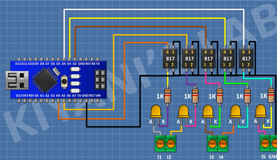
Figure 1: Isolated digital inputs with optocouplers
Since the current that Arduino’s pins could provide for digital outputs was insufficient, ULN2003 driver module was used to increase the current capacity of the outputs. In this way, up to approximately 500 mA current can be supplied to the outputs and a total of 7 digital outputs with relays are obtained. Various control units such as DC motors, servo motors, solenoid valves can be connected to these outputs and driven.
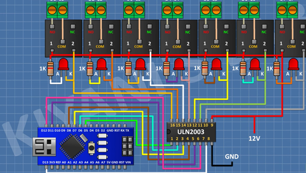
Figure 2: Digital outputs
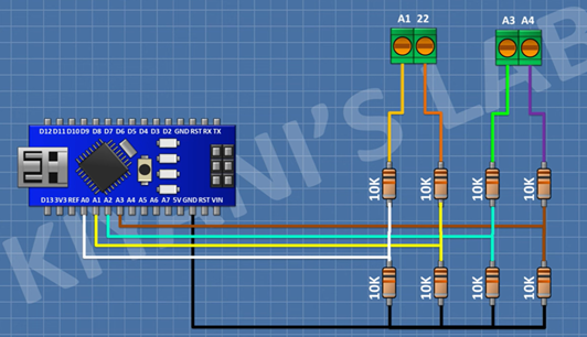
Pins A0–A4 were used to read analog signals from the sensors. 10 kΩ pull-down resistors connected to each input ensure accurate measurements by preventing the inputs from floating when left idle. Sensors with analog outputs such as temperature and pressure can be connected via the terminals. This structure allows the system to reliably detect environmental data.
After the hardware part is completed, the remaining step is to determine in software how the input and output pins will be processed. The preferred software in this project was OpenPLC. The reason why I chose OpenPLC; It is an open source platform that is compatible with PLC systems used in the industry and enables learning the Ladder Diagram (LD) programming structure. It is also an important advantage that the software is free and user-friendly.
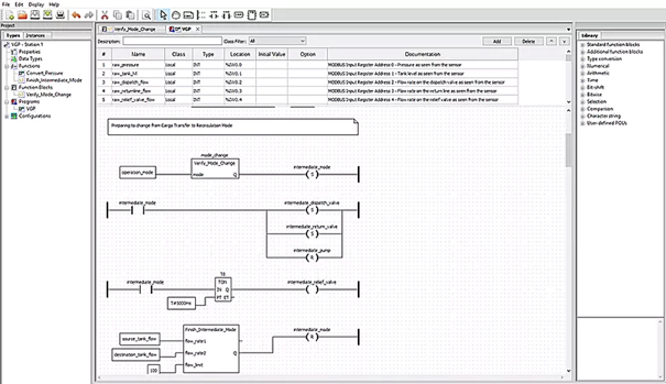
There are many resources available on the internet for those new to ladder programming. However, it may be useful to take a look at the simulation program called EKTS (Electric Control Technical Simulator) to learn the basic concepts, especially at the beginner level. An example Ladder diagram is shared below (Figure 4). Although this diagram does not belong to our project, it represents an example input-output scenario created in the OpenPLC interface.