

Traditional ANSI 50/51 protection in protection systems in energy production facilities with high short-circuit current contributions, such as thermal, hydroelectric and natural gas cycle power plants, reliably fulfills the duty of backup (back-up) protection in case of accidents. Global renewable energy increased by 2,600 GW, an increase of approximately 140% between 2015 and 2024. At the same time, with the spread of industrial facilities operated as micro-grids, this increase in renewable resources in energy conversion affects both the operation and protection philosophy of power systems.
Integration of resources such as wind and solar into the system may cause short-circuit current contributions in incidental situations to decrease and protection relays to face more complex and low production capacity scenarios. Conventional overcurrent protections (50/51) do not provide a reliable solution in systems with low short circuit currents, as they work only on a current-based principle. While this protection functions actively with current selectivity in synchronous generators with high rated power, in cases where the same production is provided by more than one wind turbine feeder or photovoltaic systems, relays may not be able to detect the fault due to blind settings.
Short circuit contribution in renewable energy sources may be insufficient in wind and solar/energy storage systems due to the following situations.
In wind facilities: Although the sub-transient short circuit currents are relatively high, due to the low production capacities and short circuit time constants, the current dissipates faster and the current level in the transient and steady state states, where protection systems often detect and clear the fault, may be insufficient.
Power systems are undergoing one of the most significant transformations in their history. The rapid integration of renewable generation, distributed energy resources, and inverter-based technologies has fundamentally altered fault behavior characteristics. Protection schemes that were once designed for large synchronous generators operating in centralized grids must now function reliably in systems where fault current levels are significantly lower and dynamic behavior is more complex.
As renewable penetration increases, traditional assumptions about short-circuit contribution, fault duration, and system inertia are no longer always valid. This shift requires protection engineers to rethink coordination strategies and adopt adaptive protection methods such as ANSI 51V (Voltage-Dependent Overcurrent), which can respond more intelligently to reduced fault current conditions.
Figure 1: Example wind facility and grid connection
On the other hand, although the high number of branches provides sufficient short-circuit current for current selectivity at network connection points, it may be insufficient in the protection of the feeder.
In solar power plants and energy storage facilitiesThere are two main reasons why short circuit currents are low in solar power plants and energy storage facilities. These can be given as the current limitation of the inverters and the increase in the voltage level (for example 0.69/34.5 kV) since they are connected to the grid with a step-up transformer.
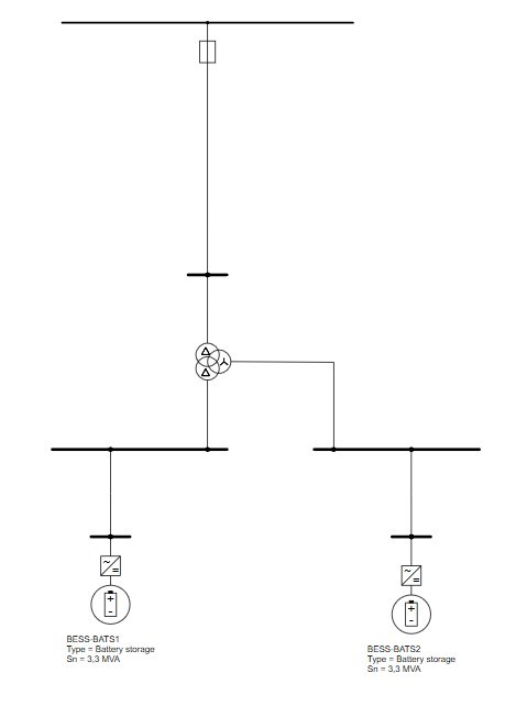
Figure 2: Example energy storage facility
With the current limiting feature of inverters, the short circuit current is generally limited to 1.15-1.5 pu. In this context, it is accepted that a maximum of 150% short circuit current will occur when performing network analyzes in common applications in the industry. The short circuit current may remain low for selectivity due to the voltage increase and transformer impedance as a result of connecting the production facility to the grid via step-up transformer.
Apart from renewable energy sources, short circuit contributions may remain low in facilities where production is carried out by synchronous generators. In cases where the excitation system of the synchronous machine is fed directly from the terminals of the generator, the excitation current decreases as the terminal voltage drops rapidly in the event of a short circuit; Due to insufficient reactive power being provided, the fault current is quickly damped.
Although the short circuit contribution is low in the above-mentioned cases, what is common to all faults is the voltage drop in incidental situations. In this context, when traditional back-up overcurrent protection is associated with voltage, voltage-controlled overcurrent protection (ANSI 51V) is used as a critical protection function in both generators and inverter-based renewable energy facilities.
IEEE Std C37.102 standard clearly emphasizes that the 51V function should be preferred in scenarios where synchronous generators can provide low short circuit current. Similarly, IEEE Std C37.91 reveals the contribution of voltage-controlled overcurrent functions to selectivity in generator-transformer units working with power transformers.
On the renewable energy side, it is defined by IEEE and IEC standards that only current-based protection functions may be insufficient due to the current limiting feature of inverter-based productions, and the necessity of voltage conditioned protection approaches is stated. Additionally, IEC 61400-21 describes the low short-circuit contribution of wind turbines and therefore recommends considering voltage-based parameters instead of current.
All these standards confirm that 51V protection plays a critical role as a reliable and selective back-up protection function not only in generators, but also in today’s networks where distributed energy sources have become widespread.
In this section, the functions of ANSI 51V protection are examined based on Siemens Siprotec 5 series protection devices. By definition, ANSI 51V is the structural voltage association of standard overcurrent protection. ANSI 51V protection, although topologically similar, has three different functional structures:
Voltage dependent inverse time overcurrent (voltage dependent)
Voltage conditioned inverse time overcurrent (voltage released)
Definite time overcurrent with undervoltage seal-in
These functions can be applied alone or together under ANSI 51V protection, depending on the characteristics of the equipment to be protected and the protection philosophy.
This is where ANSI 51V protection becomes particularly valuable. Unlike conventional overcurrent protection, ANSI 51V incorporates a voltage-dependent characteristic. When a fault occurs, system voltage drops simultaneously with the change in current. By supervising the overcurrent function with a voltage restraint or voltage-controlled logic, the relay becomes capable of detecting faults even when current magnitude alone is insufficient to exceed pickup thresholds.
In simple terms, ANSI 51V adapts its sensitivity based on the system voltage condition. As voltage decreases during a fault, the effective pickup level of the overcurrent element is reduced. This ensures reliable operation under low short-circuit current scenarios while avoiding unnecessary trips during normal load variations.
Voltage dependent inverse time overcurrent (voltage dependent) function
In conventional power plants, synchronous generators contribute substantial fault current due to their electromechanical characteristics. Their sub-transient reactance allows high initial fault currents, which makes overcurrent detection straightforward. However, inverter-based renewable energy systems behave differently. Their current contribution is typically limited by control algorithms and semiconductor switching constraints. As a result, fault currents may only slightly exceed nominal operating currents, creating a challenge for conventional overcurrent relays.
Additionally, inverter-based systems often include fault ride-through (FRT) requirements. These controls intentionally limit or shape fault current during grid disturbances to maintain stability. While beneficial for grid continuity, this behavior reduces the sensitivity margin of traditional 50/51 protection elements.
In this function, the trip threshold (threshold current Ip) of the overcurrent stage depends on the voltage magnitude. As the voltage level drops below nominal values, the starting current value decreases. This reduction occurs as a result of multiplying the measured instantaneous voltage and nominal voltage ratio by the starting current; There is a linear and directly proportional relationship. Figure-3 shows the effect of voltage ratio on starting current.
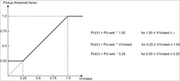
Figure 3: Voltage effect on starting current threshold
V = Measured phase-to-phase voltage
Vrated = Rated voltage
PU sett. = Starting current setting (Current Ip threshold)
PU(V) = Reduced current pickup threshold as a result of applying voltage effect
The current pickup threshold decreases proportionally to the voltage decrease. As a result, the I/Threshold-value ratio in the curve formula used for a constant current I increases and the operating time becomes shorter. In summary, when the voltage decreases, the operating curve shifts to the left and the threshold level and operating time decrease. Figure 4 shows the settings of the relevant function.
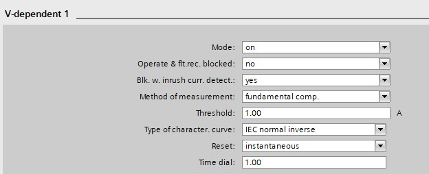
Figure 4: Voltage dependent function settings
The current set is set to approximately 20%-30% more than the highest expected operating current, depending on the operating and design characteristics of the equipment to be protected. Curve coefficient (TMS-Time Multiplier Setting) is determined by calculating from the relevant curve formula according to the opening time desired to be given as a result of coordination.
Voltage conditioned inverse time overcurrent (voltage released) function
In wind power plants, especially those using doubly-fed induction generators (DFIG) or full-converter turbine technology, fault current behavior is highly time-dependent. The sub-transient current may initially reach moderate levels, but converter control quickly limits the magnitude to protect semiconductor components. Consequently, the protection window becomes extremely narrow.
Moreover, in collector systems where multiple turbines are connected through long cable feeders, impedance values further reduce measurable fault current at relay locations. Voltage depression, however, remains a strong indicator of fault presence. Therefore, voltage-supervised overcurrent elements such as ANSI 51V provide enhanced discrimination capability in these configurations.
This stage is created in the same way as the voltage dependent inverse time overcurrent stage. The only differences are the pickup conditions and their effects on the operating curve. The function is activated when the control voltage drops below the set low voltage threshold.
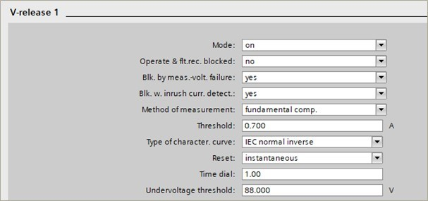
Figure 5: Voltage conditional function settings
As seen in Figure 5, the start of the protection as a voltage dependent function is conditioned to a voltage threshold (Undervoltage released). When the measured voltage falls below this threshold value, the function will be activated by applying the V/Vrated ratio to the starting current.
The current set is set to approximately 20%-30% more than the highest expected operating current, depending on the operating and design characteristics of the equipment to be protected. Curve coefficient (TMS-Time Multiplier Setting) is determined by calculating from the relevant curve formula according to the opening time desired to be given as a result of coordination.
The voltage value to be given for the condition is adjusted to the range of 75%-80% of the rated voltage, in the light of common practices and experiences. Another issue is that since voltage measurement is actively performed, it is recommended to block the protection when necessary by controlling it with the “measured voltage failure” function, which is voltage circuit supervision, in order for the protection to work correctly. This will prevent faulty trips as a result of incorrect measurements caused by the voltage transformer or secondary circuit connections rather than the system.
Definite time overcurrent (undervoltage seal-in) function with undervoltage sealing
In micro-grid applications, bidirectional power flow and varying generation levels introduce additional complexity. Fault current magnitude may change depending on whether the system is operating in grid-connected or islanded mode. During islanded operation, short-circuit levels are typically much lower, making pure overcurrent-based protection unreliable.
Voltage-dependent overcurrent protection improves selectivity in such systems by incorporating both current magnitude and system voltage profile into the decision process. This dual-parameter approach enhances coordination between feeders, distributed generators, and upstream protection devices.
This function is commonly applied in facilities where production is made with synchronous generators where fixed-time back-up overcurrent protection is provided. In generators whose excitation voltage is obtained from machine terminals, in case of close-range faults (for example in the generator or generator-transformer area), the short circuit current decreases rapidly. Due to the disappearance of the excitation voltage, the current drops below the current threshold within a few seconds. To prevent the relay from falling into the drop-out region, positive sequence voltages are used as an additional criterion in short circuit detection.
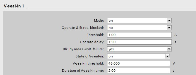
Figure 6: Undervoltage lockout function settings
If the positive sequence voltage drops below the adjustable V-seal-in threshold when the protection device receives pickup from overcurrent, the trip signal is maintained for an adjustable V-seal-in time even if the current falls below the threshold again. If the voltage returns to normal before the seal-in time expires or the low voltage sealing function is blocked via an external digital input, the sealing is broken and the pickup field relay goes into drop-out state.
The current set must be set at least 40% above the expected highest load current. Additionally, it is recommended to take the short circuit decrement curve into account when making adjustments in synchronous generators. It is recommended to block the protection when necessary by providing control with the “measured voltage failure” function, which is voltage circuit supervision like other functions based on voltage measurement.
The following formula can be used to set the sealing voltage:

In summary, ANSI 51V function can be implemented in three different structures in Siemens SIPROTEC 5 series protection devices; Thanks to its voltage-dependent, voltage-conditional and low-voltage sealing overcurrent stages, it provides reliable and selective protection in cases where short-circuit currents fade quickly or remain at low levels in both synchronous generators and inverter-based production facilities.
Conclusion
ANSI 51V protection, an advanced version of the classical overcurrent function supplemented with voltage measurement, has become critical in modern power systems due to the increasing integration of renewable energy and the low short circuit contribution of generators. As defined in IEC and IEEE series standards, 51V offers flexible solutions suitable for different equipment types and protection philosophies. In this respect, 51V is at the center of back-up protection philosophies for both grid reliability and facility security.
From a coordination perspective, ANSI 51V elements are especially useful in generator protection schemes where backup protection must remain dependable under weakened grid conditions. By dynamically adjusting time-current characteristics in response to voltage levels, the relay maintains sensitivity without compromising stability.