

In the TT system, the neutral point on the grid side is directly grounded. The grounding of the facility is carried out with a grounding electrode, independent of the network. Therefore, when there is a fault (e.g. phase contact with a device body), the fault current flows between the network ground point and the plant ground point.
The circuit through which this current passes:
► Phase-device body-ground electrode (Ra)
► Ground electrode of the distribution transformer (Rto)
► Neutral-transformer Total impedance: Ztotal=Ra +Rto +Zsoil
But R.to and Zsoil It is generally unknown and variable. In practice, the focus is on the resistance values of the earth electrode and RCD is therefore mandatory.
Earth voltage and danger threshold
Contact Voltage (Ut): Voltage occurring in contact with the human body, according to IEC 60364: If a contact voltage exceeds this value, there is a danger to life.
For example:
In a system where the grounding resistance is 100 ohms and the leakage current is 30 mA
ut: 100×0.03= 3V (Trustworthy)
In the system where the grounding resistance is 1000 ohms and the leakage current is 30 mA
ut=30V (Risky)
As a result, the lower the ground resistance, the smaller the contact voltage.
Cutting Time Requirement:
Fuses or automats trip at high short circuit currents. However, in the TT system, the fault current returning from the ground is low. Therefore, the fuse cannot reach the tripping threshold, the cut-off time exceeds the 0.2-1 second specified by the IEC standard, and this is vital. In this case a residual current protection relay is essential and typically has a threshold of 30 mA and opens the circuit within 300 ms.
RCD and Earth Resistance Relationship
In order for the residual current relay to operate safely in the system:
R.a ≤ Ul/Ircd (Ul=Permissible contact voltage, usually 50V) (Ircd= Relay threshold, e.g. 30 mA)
R.a ≤ 50/0.03= 1666.66 ohms
So theoretically, if the ground resistance is less than 1667 ohms, a 30 mA RCD will protect the system. However, in the field, this value is generally aimed to be less than 100 ohms, preferably less than 10 ohms. This is because the ground resistance is variable.
Protection Logic in TN System
Fault current path in TN system:
If there is phase contact with the body of a device, the fault current follows the following path: ” Phase-device body-PE line-transformer neutral point-transformer”
This loop rotates entirely over copper conductors, not through ground. Soil almost never comes into play.
Why is insurance sufficient?
In a TN system, the total impedance is very low.
For example:
Phase and PTO line is 30 meters away, cable cross-section is 2.5 mm² (Copper)
Resistivity of copper: 0.017 ohm.mm2/m
Total resistance: R= 0.017×60/2.5 =0.408 ohm
Fault current at 230 V voltage:
if= 230/0.408=564A
In other words, in the TN system, the fault current is very large and the fuse opens immediately. However, if the PEN line breaks, the bodies will receive phase voltage and this is very dangerous. For this reason, the use of the TN-C system in modern facilities is not recommended, TN-S or TN-CS is used and life safety is increased with RCD support.
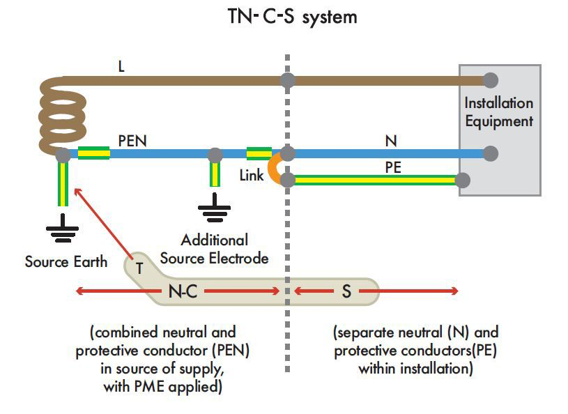
What are TN-C and TN-CS Systems?
► PE and N are transported combined throughout the facility.
► 3 phase, 1 PEN distribution is made with a total of 4 conductors.
► The PEN line carries the operating current and functions as protection.
TN-CS (Combined Separated) System
► At some point in the system (usually in the main panel) the PEN line is divided into PE and N.
► PE is now carried on a separate line, while neutral continues on its own path.
► There will be a total of 5 conductors: 3 phases, 1 neutral and 1 ground.
► This structure is preferred in modern installations.
► According to TS HD 60364, this structure is considered mandatory.
► PEN conductor only 10 mm according to TS HD 60364 and IEC2 Cu or 16mm2 It can be separated when it is al and above.
How to see it in practice?
There is usually a PEN bus in the switchboard. This busbar is connected to ground (electrode with strip), and a jumper cable goes to the N busbar. The next installation is now 5 wires.
Conclusion
The safety of an electrical installation is ensured not only by cable cross-sections or device selection, but also by the correct construction of the grounding system underlying the infrastructure. TT and TN systems are two different approaches to this infrastructure, each with its own advantages and disadvantages. Today, engineering means understanding, interpreting and evaluating the system on site. Therefore, whether a new facility is established or an old system is inspected, the grounding system used must be identified correctly and appropriate protection elements must be determined accordingly. Grounding is not a detail but a vital line. Knowing where he stands saves lives.